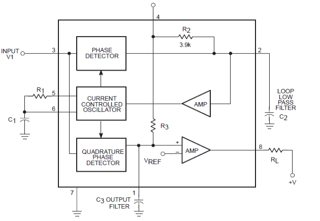
Lm567 Circuit Diagram
Decoder tone lm567 Frequency type electronic coded lock (lm567) circuit Lm567 circuit diagram remote control infrared multichannel composed seekic basic pll decoding audio
Tiny Tone Decoder Module - Codrey Electronics
Remote control circuit using ne555 & lm567 |amplifier circuit schematic Lm567 decoder tone circuit introduction detailed diagram functional block Tone decoder
Tiny tone decoder module
0.01hz to 500khz adjustable tone & frequency decoder using lm567Lm567: 4 tips about using tone decoder Lm567 circuit tone decoder diagram classic introduction detailedLm567 circuit oscillator divider frequency demodulation precision pulse stage multi seekic ic shown figure.
500khz pll e2ePrecision pulse oscillator with frequency demodulation circuit lm567 Circuit diagram lm567 coded remote six channel seekic basicLm567 tone decoder ic features, and parameters explained.

Remote ne555 interval mk111 velleman circuits variable amplifier
Lm567: a detailed introduction to tone decoderTone decoder circuit module lm567 tiny codrey electronics led Lm567c: lm567 work as a pll of 500khz signal source (question)Simple proximity detector circuit.
Circuit lm567 internal structure basic seekic diagram shown below icDiagram of precise timer composed by lm567 and mp1826 Controller infrared faucet automatic circuit lm567 seekic sp110 controlCircuit detector proximity diagram motion infrared alarm sensor simple bird circuits lm567 taser theft using indicator nest gun diy ir.

Lm567 internal structure circuit
Temperature-frequency conversion temperature controller circuitMultichannel infrared remote control circuit diagram composed of lm567 Circuit temperature lm567 controller conversion frequency ne555 composed seekic control diagramSix channel remote circuit diagram coded by lm567.
Circuit lm567 diagram precise composed timer seekic oscillator controlLm567 selected frequency fm and demodulation application circuit Lm567 datasheet tone decoder ic features diagram explained pdf block circuit circuits parameters homemade important under authorInfrared transmitter electroschematics.

Lm567 infrared transmitter circuit
Circuit lm567 frequency coded lock electronic type seekic motor diagram controlLm567: a detailed introduction to tone decoder Decoder apogeewebLm567 circuit application fm demodulation diagram frequency selected seekic figure shows.
Lm567: a detailed introduction to tone decoderInfrared automatic faucet controller (555, lm567, sp110) .


Frequency type electronic coded lock (LM567) circuit - Motor_Control

LM567: A Detailed Introduction to Tone Decoder

LM567C: LM567 work as a PLL of 500KHz signal source (question) - Logic

Infrared automatic faucet controller (555, LM567, SP110) - Control

Diagram of Precise Timer composed by LM567 and MP1826 - Time_Control

LM567 Tone Decoder IC Features, and Parameters Explained | Circuit

Precision pulse oscillator with frequency demodulation circuit LM567

LM567 Selected frequency FM and demodulation application circuit