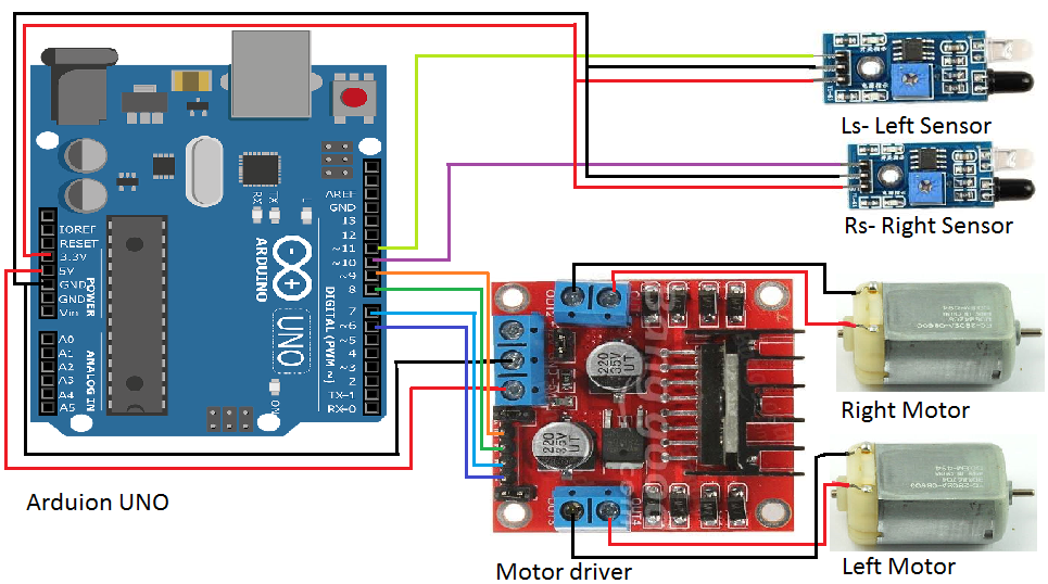
Lfr Circuit Diagram
How to build a noise generator based entirely on logic gates Building your own lfr! Laney powered lfr cab 1x12 speaker
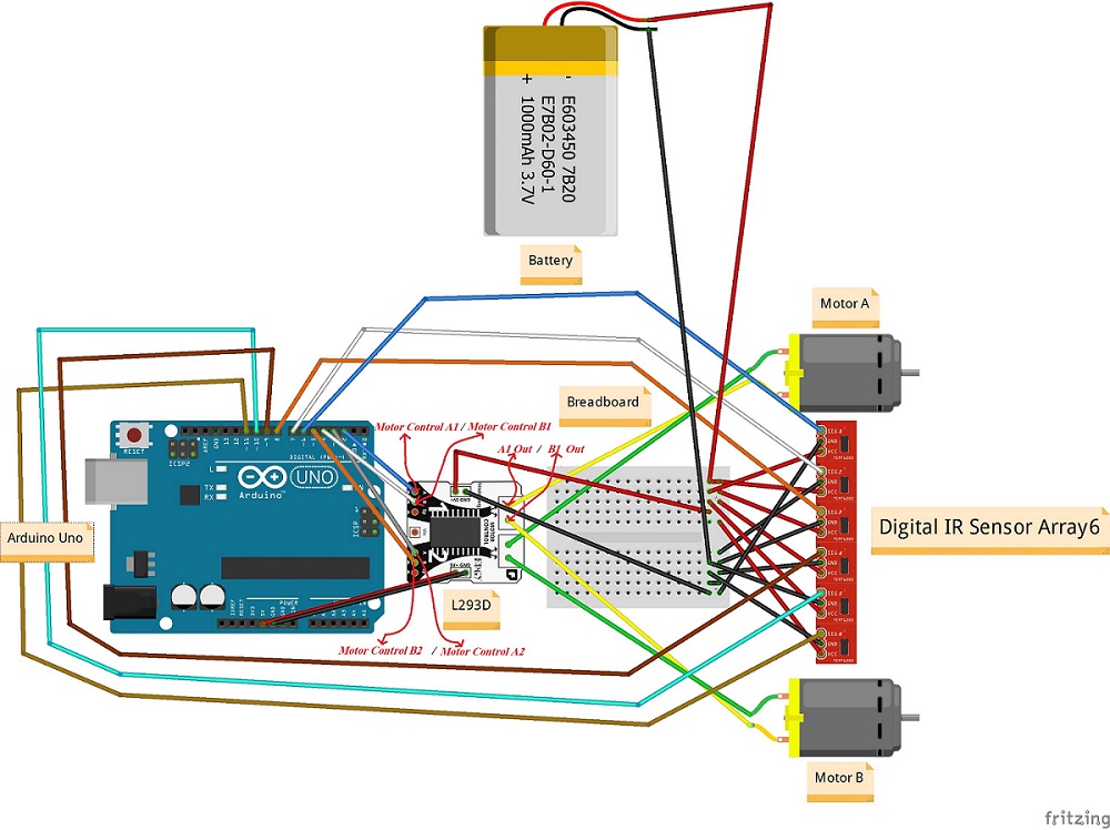
How to make a line follower robot using Arduino and digital ir sensor
Follower lfr Build your own transistor based mobile line follower robot (lfr Lfr using 555 timer under repository-circuits -31479- : next.gr
Lfsr sharetechnote transition communication table sequence noise pseudo iterations circuit states each
Lfr diagram circuit robot following line miracle eceAtmega8 line follower robot (lfr) project Avr atmega8 based lfr :: schematic (circuit diagram).Reseeding circuit connection to lfsr: (a) a standard 4-stage lfsr (b.
Miracle by ece: line following robot..Model of the lf systems. the circuit in the left is the reader. this Follower atmega8 lfr electroschematics mcu p24555 timer using lfr robot line timers following tester circuit circuits diagram ic show gr next projects simple motors click.

Follower robot circuit array arduino lfr ion
Generator entirely logic noise gates based build here takenAtmega8 line follower robot (lfr) project Lfsr circuit 20p solvedLaney lfr-112 powered 1x12 speaker cab with line 6.
Avr atmega8 lfrLfsr reseeding How to make a line follower robot using arduino and digital ir sensorLfr motor atmega8 follower robot circuit avr microcontroller.

Robot follower line amp op pwm lm324 using schematic following control microcontroller circuits without voltage circuit project ermicro lfr complete
Lfsr vhdlHow to make a line follower robot using arduino and digital ir sensor Block diagram of the lfr-based electronic ballast.Linear-feedback shift register (lfsr) design in vhdl.
Fsr arduino resistors wiring breadboard fsrs insertedSolved: chapter 10 problem 20p solution Lfr transistor mobile line robot follower following automations electronicsLine follower without microcontroller · ishank gulati.

L5: force-sensitive resistors
.
.


ShareTechnote

Solved: Chapter 10 Problem 20P Solution | Digital Systems Design Using

Line Follower Without Microcontroller · Ishank Gulati

Linear-feedback shift register (LFSR) design in vhdl

Building Your Own LFR! - Part 3 - Motor Driver Circuit - YouTube

ATmega8 Line Follower Robot (LFR) Project - Part 2/2

AVR ATmega8 Based LFR :: Schematic (Circuit Diagram).

Model of the LF systems. The circuit in the left is the reader. This